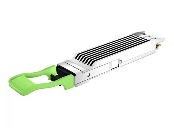
How Does an 800GBASE-LR8 OSFP Transceiver Support 10km Ethernet Connectivity?
As data center networks expand, the demand for higher bandwidth and longer-distance connectivity continues to grow. Cloud computing, distributed applications, and artificial intelligence workloads require reliable communication between switches, servers, and facilities. While short-reach optical solutions are suitable for connections within a rack or data hall, links spanning longer distances require transceivers designed to maintain signal quality over single-mode fiber. An 800G optical solution can provide the bandwidth needed for these increasingly demanding network environments.
Choosing a transceiver involves more than comparing data rates. Network engineers must consider optical architecture, transmission distance, connector interfaces, equipment compatibility, and thermal requirements. The appropriate solution should match both the physical fiber infrastructure and the capabilities of the host switch. These factors become particularly important when deploying 800G Ethernet links across large data centers or between separate network facilities.
Designed for high-speed Ethernet connectivity, 800G OSFP modules can support high-bandwidth network deployments when paired with compatible equipment. An 800GBASE-LR8 implementation targets long-reach optical transmission over single-mode fiber, with a nominal reach of up to 10 km under specified conditions. For a dual-port module described as 800GBASE-LR8 (2×400G LR4), however, engineers should verify the exact optical architecture and per-port specifications before deployment, as two 400G links are not automatically equivalent to one standardized 800GBASE-LR8 link.
What Is an 800GBASE-LR8 OSFP Transceiver?
An 800GBASE-LR8 transceiver is intended to provide 800 Gigabit Ethernet connectivity over single-mode fiber using a long-reach optical architecture. The LR8 designation generally refers to eight optical wavelength channels operating within the 1310 nm region. Through wavelength-division multiplexing, multiple optical channels can share a fiber pair, allowing high aggregate bandwidth without requiring a separate fiber pair for every wavelength.
The OSFP form factor is designed for high-speed network equipment that supports compatible optical modules. Its mechanical design, electrical interface, and thermal characteristics must align with the host switch. Although OSFP modules are commonly used in high-capacity Ethernet platforms, the form factor alone does not guarantee support for every 800G optical standard or every switch model.
How Does the LR8 Optical Architecture Work?
In a typical eight-wavelength 800G optical implementation, each optical channel carries a portion of the aggregate data stream. The transmitter generates the optical signals, combines the wavelengths for transmission, and sends them through single-mode fiber. At the receiving end, the module separates the wavelengths and converts the received optical signals back into electrical signals for the host device.
PAM4, or four-level pulse-amplitude modulation, enables each symbol to represent two bits of information. This increases the amount of data that can be transmitted per symbol compared with binary NRZ signaling at a similar symbol rate. However, PAM4 also places demanding requirements on signal quality and receiver performance, making appropriate optical design and link validation essential.
Why Is 1310nm Single-Mode Fiber Suitable for 10km Links?
The 1310 nm wavelength region is widely used in single-mode optical communication. Single-mode fiber carries light primarily through one propagation mode, reducing modal dispersion and supporting longer transmission distances than typical multimode data center links. These characteristics make it suitable for high-speed connections between network devices located in different parts of a campus or data center facility.
A nominal 10 km reach gives network designers flexibility when planning links that extend beyond a single rack or data hall. Depending on the topology, these connections may link aggregation switches, connect separate buildings, or support data center interconnect applications. The actual suitability of a link depends on the transceiver specification, fiber quality, connector losses, and total optical power budget.
Why Does the Optical Link Budget Matter?
A transceiver’s reach rating assumes that the optical channel satisfies the relevant operating requirements. Every connector, patch panel, splice, and fiber segment can contribute insertion loss. As the number of connections increases, the total loss may approach or exceed the link’s allowable budget, even when the physical distance remains below 10 km.
Before deployment, engineers should calculate or measure the total channel loss and compare it with the module’s specifications. They should also confirm the supported fiber type and connector interface. Proper cleaning and inspection of optical end faces can reduce avoidable losses and help maintain stable link performance.
What Does the 2×400G LR4 Configuration Mean?
A dual-port module described as 800GBASE-LR8 (2×400G LR4) combines two 400G LR4 connections to provide an aggregate bandwidth of 800 Gb/s. Each port operates as a separate 400G link, subject to the module’s actual design and host-device support. This configuration differs from a single-port 800GBASE-LR8 implementation, even though both descriptions contain the terms 800G and LR8.
A typical 400GBASE-LR4 link uses four optical wavelengths to carry 400G Ethernet traffic over a duplex single-mode fiber connection. In a dual-port design, the two 400G connections may support separate links to compatible devices or ports, depending on the network topology. Engineers should not assume that both ports share a single optical channel or that one port can independently deliver 800G.
This distinction matters when planning switch capacity, fiber routing, and equipment interoperability. Before selecting a module, verify the manufacturer’s port mapping, wavelength configuration, optical specifications, and supported link modes. These details determine how the module should be connected and whether it matches the intended Ethernet architecture.
How Does OSFP Support High-Density Ethernet Switching?
High-density Ethernet switches must accommodate increasing bandwidth while managing space, power, and heat. OSFP is designed for high-speed connectivity in compatible network platforms, enabling equipment manufacturers to integrate fast electrical interfaces and optical modules into dense front-panel configurations. The exact port density and supported speeds depend on the switch model and its hardware design.
Thermal management is particularly important as transceiver data rates increase. A module described as having an integrated heat sink and closed finned top is designed around specific mechanical and thermal requirements. When installing an optical transceiver in an air-cooled switch, engineers should follow the platform manufacturer’s guidance for supported module types, power limits, and cooling conditions. A matching connector does not, by itself, establish full compatibility.
What Should You Check Before Deploying an 800GBASE-LR8 Module?
Compatibility should be verified before installation. Confirm that the switch supports the module’s exact form factor, optical standard, port configuration, and firmware requirements. For modules intended for NVIDIA Spectrum-4 Ethernet switches, use validated compatibility information for the specific switch model and hardware configuration rather than relying solely on the product’s nominal data rate.
The fiber infrastructure must also match the module’s optical interface and reach requirements. Check the connector type, fiber specification, channel loss, and intended link distance. For a dual-port 2×400G LR4 module, confirm that both ports are connected and configured according to the manufacturer’s documentation. Digital diagnostics monitoring, when supported by the module and host, can help track optical transmit and receive power, temperature, and other operating parameters.
Finally, test the installed links before placing them into production. Checking link status, error counters, and optical diagnostic readings can help identify issues involving cabling, port configuration, or signal quality. A structured validation process reduces troubleshooting time and helps ensure that the deployed network meets its performance requirements.
Conclusion
An 800GBASE-LR8 optical solution can support high-bandwidth Ethernet connectivity over single-mode fiber at distances of up to 10 km when the complete optical channel meets the applicable specifications. Its long-reach capability makes it relevant to large data centers, campus networks, and suitable data center interconnect applications.
For a dual-port module specified as 2×400G LR4, the two 400G connections and their optical architecture must be evaluated separately from a single-port 800GBASE-LR8 design. By verifying the port configuration, fiber link budget, OSFP compatibility, and thermal requirements, network engineers can select an appropriate 800G solution for their deployment.